Functional safety is frequently perceived as an abstract industrial concept restricted to high-integrity chemical plants, nuclear facilities, and heavy robotic assembly lines. In reality, the exact same core architectural principles , sensor inputs, vital logic solvers, and actuator execution to achieve a defined safe state are embedded into everyday commercial and consumer technology to protect the public from systematic failures and operational hazards.
Under major safety standards, functional safety focuses explicitly on active systems. Unlike passive safety elements such as vehicle crumple zones or safety helmets, an active safety system must detect a dangerous condition, process the data, and execute a dynamic response to mitigate or eliminate the risk.
Technical Analysis of Everyday Functional Safety Loops
1. Electric Pressure Cookers and Thermal Runaway Prevention (IEC 60335-2-15)
Traditional pressure cookers relied entirely on mechanical weight valves to bleed off excess steam pressure. While these mechanical overrides remain as secondary protection, modern electric pressure cookers utilize automated electronic safety functions governed by IEC 60335-2-15 (particular requirements for appliances for heating liquids) and IEC 60335-1 Annex H (safety of programmable electronic circuits).
The primary hazard is a structural explosion caused by runaway pressure profiles. To mitigate this risk without relying on human intervention, the appliance features an electronic safety loop:

The Sensor:
A Negative Temperature Coefficient (NTC) thermistor or a dedicated pressure transducer continuously monitors the internal cooking environment.
The Logic Solver:
The internal microprocessor runs safety algorithms mapped to Annex H requirements, evaluating the rate of temperature rise against pre-programmed pressure curves.
The Actuator:
If the logic solver detects a thermal or pressure limit breach, it commands a dedicated electromechanical relay to open. This immediately removes electrical power from the heating element, neutralizing the hazard before the mechanical relief valve is forced to actuate.
2. Elevator Passenger Protection Systems (ASME A17.1 / EN 81-20)
Vertical transit systems utilize active safeguarding systems to prevent mechanical crushing injuries when passengers cross the door plane. These functions comply with international elevator safety codes, including ASME A17.1 in North America and EN 81-20/50 in Europe.
The specific safety function prevents the door panels from exerting dangerous closing forces if an obstruction is present:

The Sensor:
Modern elevators deploy an infrared light curtain array or a 3D Time-of-Flight (ToF) sensor embedded in the door edges. These sensors project multiple intersecting beams across the opening plane.
The Logic Solver:
The door controller subsystem continuously monitors the state of the light receiver matrix.
The Actuator:
Breaking any light beam causes the logic solver to interrupt the closing sequence instantly. It commands the drive motor inverter to reverse torque, opening the door panels before they make physical contact with a passenger or object. Under modern standards, these control units incorporate diagnostic monitoring; if the sensor array fails internally, the system defaults to a safe state, forcing the doors to remain open and preventing transit.
3. Automotive Autonomous Emergency Braking (ISO 26262 / ASIL D)
Advanced Driver Assistance Systems (ADAS), such as Autonomous Emergency Braking (AEB), operate in highly dynamic environments where failures carry catastrophic risks. Because a failure to brake or an unintended phantom braking event can result in fatal collisions, the system architecture is engineered under ISO 26262 and rated at Automotive Safety Integrity Level D (ASIL D)—the highest risk classification in the automotive domain.
The AEB safety function continuously calculates the risk of front-end impacts:

The Sensor:
Dual-technology sensor inputs, typically combining long-range radar and a forward-facing stereoscopic camera, feed real-time velocity and distance tracking data into the vehicle network.
The Logic Solver:
The ADAS Electronic Control Unit (ECU) runs predictive algorithms calculating Time-to-Collision (TTC).
The Actuator:
If the driver does not respond to preliminary audible and visual warnings, the ECU communicates over a high-speed automotive bus to command the Electronic Stability Control (ESC) hydraulic modulator. The ESC directly pressurizes the brake calipers to decelerate the vehicle at maximum capacity, bypassing human physical reaction lag to mitigate the impact.
4. Automated Railroad Grade Crossings (CENELEC EN 50129 / SIL 4)
Automated railway grade crossings represent a pure application of fail-safe functional safety design. Governed by the CENELEC railway standards framework (EN 50126, EN 50128, and EN 50129), these trackside systems are built to meet Safety Integrity Level 4 (SIL 4) targets.
The safety goal is to isolate vehicular and pedestrian traffic from an approaching train:

The Sensor:
Axle counters or electrical track circuits are embedded into the rail infrastructure at a calculated distance before the crossing to detect the physical presence of a train via wheel-to-rail shunting.
The Logic Solver:
The detection signal drops a vital relay or interfaces with a fail-safe, hardware-redundant solid-state interlocking controller.
The Actuator:
To guarantee execution during a total system power outage, the crossing gates are held in the raised position by active, continuous electrical power. When the vital logic solver registers a train approach, it cuts power to the mechanism. The crossing gate arms lower automatically via gravity counterweights, deploying a physical barrier across the roadway even if the municipal power grid is completely down.
5. Domestic and Commercial Clothes Dryers (IEC 60335-2-11)
Thermal management systems in clothes dryers prevent fires caused by lint accumulation, restricted exhaust paths, or air duct blockages. These appliances are regulated under IEC 60335-2-11, requiring independent layers of functional protection to isolate heating elements during high-temperature anomalies.
The protection strategy implements a dual-layer safety circuit:
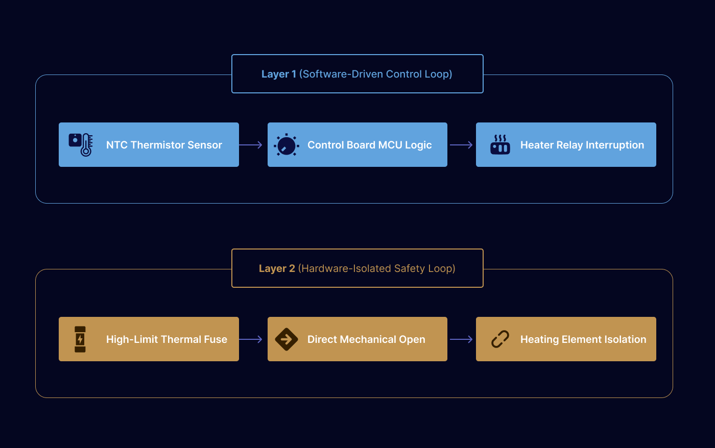
Layer 1 (Software-Driven System):
An NTC thermistor monitors the active exhaust airflow temperature. The primary control board microcontroller reads this voltage change and opens the inline heater relay if temperatures cross standard thresholds.
Layer 2 (Hardware-Isolated System):
To safeguard against a frozen microcontroller or a welded heater relay contact, an independent mechanical thermal cut-out switch or single-use thermal fuse is placed directly in series with the main heating element power line. If the temperature hits a critical threshold, the device opens mechanically, breaking the electrical path to the heating coils immediately without software intervention.